Why Use F-RAM for Event Data Recorders?
The event data recorder (EDR) installed in a vehicle can be referred to as the automotive black box for safety and monitoring purposes. Yet, it has never been considered as a feature in the buying of a new car compared to other automotive features: It does not provide the thrill that a high-performance V8 engine gives, and while potential car buyers are normally interested in a new car’s infotainment system, it would be most unusual if they paid any attention to the EDR.
Nevertheless, the EDR is set to become more critical as more semi-autonomous and fully autonomous vehicles go on public roads for testing and, eventually, as production models for the masses. In these vehicles, the camera and sensor data stored in the EDR as part of the ADAS system will play a crucial role in:
establishing fault and liability for damages suffered in road accidents by collecting last-second information
providing data that helps vehicle makers improve the design of autonomous driving systems when an incident occurs
informing legislators’ approaches to the setting of regulations for autonomous vehicles on public roads based on statistical event data collected
This means that the specification and operation of EDRs is of great interest to automotive OEMs as well as the insurance industry and to governments. The EDR needs to record data on an ongoing basis but only needs to capture the last event, which requires fast write times and its ability to retain the last event data under harsh environments. Reliability and performance are key characteristics that are important for EDR.
The requirement for fail-safe storage brings us to the complexity of today’s flash- or EEPROM-based EDR designs. The risk of losing data in certain circumstances is leading automotive manufacturers to take a new interest in a different, and proven, non-volatile memory technology such as ferroelectric RAM, or F-RAM. The attributes of F-RAM — its instant write capability, infinite endurance, high data integrity, and harmony with functional safety requirements — are ideally suited to new and more reliable EDR applications.
This article examines the case for replacing flash or EEPROM with F-RAM and the requirements that F-RAM devices will need to satisfy if they are to be successfully integrated in new automotive EDR designs.
EDR requirements: high speed and high reliability
The essential functional requirement of a vehicle’s EDR is to capture all specified data inputs — from sensing devices such as visible light and infrared cameras and radar and LiDAR sensors and from input devices such as the throttle, brake pedal, and steering wheel. It should capture these inputs before and during a safety event such as a collision with another vehicle, providing crash investigators with a complete picture of the vehicle’s movement before an accident takes place. This data-capture capability needs to be fail-safe, guaranteeing that data is stored under any conditions, including failure of the vehicle’s electrical power system. The data-storage function should also be able to withstand mechanical damage to other vehicle sub-systems and even to the EDR itself.
Undesirable workarounds in conventional EDR designs
To meet strict specifications for the operation of EDRs, automotive manufacturers have, until now, chosen to adopt an architecture based on familiar non-volatile memory technologies that offer a very low unit cost per bit: EEPROM or flash. But both technologies suffer from various drawbacks in the way that they operate: the most important for EDRs is that their write speed is very slow and their endurance — the number of program/erase cycles that they can perform before they wear out — is low. This means that EDR implementations based on EEPROM or flash need to be buttressed by various workarounds involving additional components and complex software running in a host system-on-chip (SoC) or microcontroller.
These workarounds typically include:
An SRAM or DRAM buffer. These volatile memory technologies offer a much faster write speed than flash or EEPROM, so they close the time gap that otherwise exists between the processing of sensor data at the SoC and its storage in non-volatile memory.
Capacitors to provide an emergency backup power source to supply the buffer memory and flash or EEPROM. This protects against the risk of system power supply failure in the event of a crash.
Wear-leveling software in the SoC. The function of these complex algorithms is to spread the physical location of write operations equally across all memory cells in an EEPROM or flash device.
These workarounds are highly undesirable. The provision of additional components adds to the system’s bill-of-materials (BOM) cost. The extra component count also adds to the complexity of the board assembly, increasing system size and weight.
When a vehicle’s single EDR is located under the hood or behind the dashboard, this extra size is not an insurmountable drawback. But in the new generation of autonomous vehicles, an EDR may be mounted close to sensor devices — for instance, in the rearview mirror assembly or within the ADAS system near the cameras. Here, size is of great concern.
The workarounds also increase design complexity and design risk. Wear-leveling software can extend an EEPROM or flash device’s endurance, but the number of program/erase cycles that may occur in a vehicle’s lifetime cannot be known, only estimated. So the design team must choose between over-specifying memory capacity, resulting in fewer program/erase cycles per megabyte of available capacity but raising BOM cost, or optimizing for cost but at the risk of premature memory wear-out.
A similar tradeoff applies to capacitors operating as a backup power supply: They have a limited lifespan and age more quickly at high temperatures. Again, the lower-risk option is to over-provision capacitance to allow for premature failure of some capacitor units, but this further increases BOM budget and space.
F-RAM for infinite endurance and instant write
These are the painful and, in some cases, unacceptable, compromises entailed in implementing workarounds for the use of flash and EEPROM in automotive EDRs. As a result, interest in F-RAM non-volatile memory technology for automotive EDRs has been sparked because its use addresses those shortcomings. F-RAM memory offers instant write capability, unlimited endurance, and near-zero soft error rates to support compliance with functional safety standards.
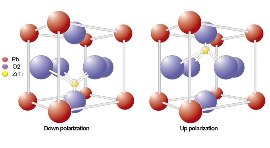
These attractive characteristics are the result of the ferroelectric properties of a class of materials of which lead zirconate titanate (PZT) is one. PZT has a perovskite crystal structure with a cation in the center (see Figure 1). This cation can be in one of two positions, and the position can be switched by the application of an electric field. Each transition produces a “switch charge” (Qs), which may be read to signal a logical 1 or 0.

Figure 1: F-RAM stores data by polarization of the ferroelectric material PZT. (Source: Cypress Semiconductor)
The operation of a ferroelectric memory is completely different from that of a traditional writable non-volatile memory derived from floating gate technologies, which work by storing charge in a bit cell. Flash or EEPROM memories use charge pumps to generate high voltages on-chip (10 V or more) and force charge carriers through the gate oxide. This produces long write delays and requires high write power, which is destructive to the memory cell.
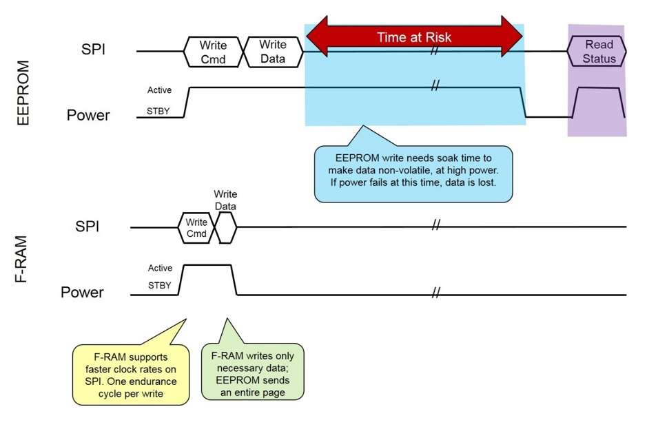
By contrast, the write speed for F-RAM is effectively instant — a matter of a few picoseconds. Because of its short duration, this write operation can be powered by the inherent capacitance of an F-RAM memory chip. This means that, once data is presented to the device’s pins, it is guaranteed to be stored even if the system power supply fails — and with no need for a capacitor or any other external power source. The instant write speed also means that there is no need for a high-speed buffer SRAM or DRAM memory on the board (see Figure 2).
The ferroelectric principle also gives unlimited endurance. For example, an Excelon-Auto F-RAM memory device from Cypress Semiconductor is rated for 100 trillion write cycles. This is sufficient to enable it to log data every 10 µs for 20 years, with no requirement for complex wear-leveling software.
An effective automotive EDR implementation will pair an unlimited-endurance F-RAM device, which is available in densities of 2 Mb or 4 Mb, with high-density flash. The memory will typically be configured to continuously store the most recent 1 to 5 s of data, while a flash memory array is used for bulk storage of older data. In the case of the Excelon-Auto device, there is a serial peripheral interface, and it uses standard non-volatile commands for configuration and read and write operations.

Figure 2: The fast write speed of F-RAM protects critical data that may be lost when using an EEPROM device.
Compatible with automotive safety and quality standards
The operational benefits of F-RAM in automotive EDRs are clear, but automotive designers must have regard for quality and safety as well as performance considerations. An experienced supplier to the automotive industry will typically exceed performance requirements — the Cypress F-RAM devices are AEC-Q100–qualified to a maximum temperature of 85°C or 125°C, for example — and also hold all of the necessary certifications such as TS16949, support PPAP processes, and maintain joint qualifications with specific customers.
Compliance to the ISO 262626 functional safety standard is also a necessity, so detailed reliability reports and quality documentation are expected by customers. In the case of the Excelon-Auto devices, failure-in-time (FIT) rates fall a long way below the threshold required at the component level by the ISO 26262 specifications. Embedded error correction code (ECC), which ensures that soft error rates in write and read operations are close to zero, is also far superior to that of flash or EEPROM devices.
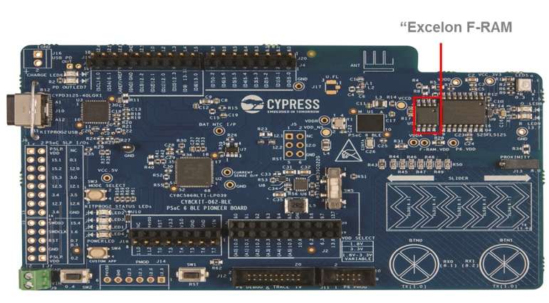
In conclusion, automotive-qualified F-RAM memory devices are available today for use in EDRs, providing the fast operation and long endurance required to store a vehicle’s sensor data up to the very last moment before an incident with no need for expensive buffer memories and backup power supplies. The use of F-RAM in automotive EDRs produces a simpler, smaller, and better-performing design than the conventional flash- or EEPROM-based approaches do (see Figure 3).

Nevertheless, the EDR is set to become more critical as more semi-autonomous and fully autonomous vehicles go on public roads for testing and, eventually, as production models for the masses. In these vehicles, the camera and sensor data stored in the EDR as part of the ADAS system will play a crucial role in:
establishing fault and liability for damages suffered in road accidents by collecting last-second information
providing data that helps vehicle makers improve the design of autonomous driving systems when an incident occurs
informing legislators’ approaches to the setting of regulations for autonomous vehicles on public roads based on statistical event data collected
This means that the specification and operation of EDRs is of great interest to automotive OEMs as well as the insurance industry and to governments. The EDR needs to record data on an ongoing basis but only needs to capture the last event, which requires fast write times and its ability to retain the last event data under harsh environments. Reliability and performance are key characteristics that are important for EDR.
The requirement for fail-safe storage brings us to the complexity of today’s flash- or EEPROM-based EDR designs. The risk of losing data in certain circumstances is leading automotive manufacturers to take a new interest in a different, and proven, non-volatile memory technology such as ferroelectric RAM, or F-RAM. The attributes of F-RAM — its instant write capability, infinite endurance, high data integrity, and harmony with functional safety requirements — are ideally suited to new and more reliable EDR applications.
This article examines the case for replacing flash or EEPROM with F-RAM and the requirements that F-RAM devices will need to satisfy if they are to be successfully integrated in new automotive EDR designs.
EDR requirements: high speed and high reliability
The essential functional requirement of a vehicle’s EDR is to capture all specified data inputs — from sensing devices such as visible light and infrared cameras and radar and LiDAR sensors and from input devices such as the throttle, brake pedal, and steering wheel. It should capture these inputs before and during a safety event such as a collision with another vehicle, providing crash investigators with a complete picture of the vehicle’s movement before an accident takes place. This data-capture capability needs to be fail-safe, guaranteeing that data is stored under any conditions, including failure of the vehicle’s electrical power system. The data-storage function should also be able to withstand mechanical damage to other vehicle sub-systems and even to the EDR itself.
Undesirable workarounds in conventional EDR designs
To meet strict specifications for the operation of EDRs, automotive manufacturers have, until now, chosen to adopt an architecture based on familiar non-volatile memory technologies that offer a very low unit cost per bit: EEPROM or flash. But both technologies suffer from various drawbacks in the way that they operate: the most important for EDRs is that their write speed is very slow and their endurance — the number of program/erase cycles that they can perform before they wear out — is low. This means that EDR implementations based on EEPROM or flash need to be buttressed by various workarounds involving additional components and complex software running in a host system-on-chip (SoC) or microcontroller.
These workarounds typically include:
An SRAM or DRAM buffer. These volatile memory technologies offer a much faster write speed than flash or EEPROM, so they close the time gap that otherwise exists between the processing of sensor data at the SoC and its storage in non-volatile memory.
Capacitors to provide an emergency backup power source to supply the buffer memory and flash or EEPROM. This protects against the risk of system power supply failure in the event of a crash.
Wear-leveling software in the SoC. The function of these complex algorithms is to spread the physical location of write operations equally across all memory cells in an EEPROM or flash device.
These workarounds are highly undesirable. The provision of additional components adds to the system’s bill-of-materials (BOM) cost. The extra component count also adds to the complexity of the board assembly, increasing system size and weight.
When a vehicle’s single EDR is located under the hood or behind the dashboard, this extra size is not an insurmountable drawback. But in the new generation of autonomous vehicles, an EDR may be mounted close to sensor devices — for instance, in the rearview mirror assembly or within the ADAS system near the cameras. Here, size is of great concern.
The workarounds also increase design complexity and design risk. Wear-leveling software can extend an EEPROM or flash device’s endurance, but the number of program/erase cycles that may occur in a vehicle’s lifetime cannot be known, only estimated. So the design team must choose between over-specifying memory capacity, resulting in fewer program/erase cycles per megabyte of available capacity but raising BOM cost, or optimizing for cost but at the risk of premature memory wear-out.
A similar tradeoff applies to capacitors operating as a backup power supply: They have a limited lifespan and age more quickly at high temperatures. Again, the lower-risk option is to over-provision capacitance to allow for premature failure of some capacitor units, but this further increases BOM budget and space.
F-RAM for infinite endurance and instant write
These are the painful and, in some cases, unacceptable, compromises entailed in implementing workarounds for the use of flash and EEPROM in automotive EDRs. As a result, interest in F-RAM non-volatile memory technology for automotive EDRs has been sparked because its use addresses those shortcomings. F-RAM memory offers instant write capability, unlimited endurance, and near-zero soft error rates to support compliance with functional safety standards.
These attractive characteristics are the result of the ferroelectric properties of a class of materials of which lead zirconate titanate (PZT) is one. PZT has a perovskite crystal structure with a cation in the center (see Figure 1). This cation can be in one of two positions, and the position can be switched by the application of an electric field. Each transition produces a “switch charge” (Qs), which may be read to signal a logical 1 or 0.

Figure 1: F-RAM stores data by polarization of the ferroelectric material PZT. (Source: Cypress Semiconductor)
The operation of a ferroelectric memory is completely different from that of a traditional writable non-volatile memory derived from floating gate technologies, which work by storing charge in a bit cell. Flash or EEPROM memories use charge pumps to generate high voltages on-chip (10 V or more) and force charge carriers through the gate oxide. This produces long write delays and requires high write power, which is destructive to the memory cell.
By contrast, the write speed for F-RAM is effectively instant — a matter of a few picoseconds. Because of its short duration, this write operation can be powered by the inherent capacitance of an F-RAM memory chip. This means that, once data is presented to the device’s pins, it is guaranteed to be stored even if the system power supply fails — and with no need for a capacitor or any other external power source. The instant write speed also means that there is no need for a high-speed buffer SRAM or DRAM memory on the board (see Figure 2).
The ferroelectric principle also gives unlimited endurance. For example, an Excelon-Auto F-RAM memory device from Cypress Semiconductor is rated for 100 trillion write cycles. This is sufficient to enable it to log data every 10 µs for 20 years, with no requirement for complex wear-leveling software.
An effective automotive EDR implementation will pair an unlimited-endurance F-RAM device, which is available in densities of 2 Mb or 4 Mb, with high-density flash. The memory will typically be configured to continuously store the most recent 1 to 5 s of data, while a flash memory array is used for bulk storage of older data. In the case of the Excelon-Auto device, there is a serial peripheral interface, and it uses standard non-volatile commands for configuration and read and write operations.

Figure 2: The fast write speed of F-RAM protects critical data that may be lost when using an EEPROM device.
Compatible with automotive safety and quality standards
The operational benefits of F-RAM in automotive EDRs are clear, but automotive designers must have regard for quality and safety as well as performance considerations. An experienced supplier to the automotive industry will typically exceed performance requirements — the Cypress F-RAM devices are AEC-Q100–qualified to a maximum temperature of 85°C or 125°C, for example — and also hold all of the necessary certifications such as TS16949, support PPAP processes, and maintain joint qualifications with specific customers.
Compliance to the ISO 262626 functional safety standard is also a necessity, so detailed reliability reports and quality documentation are expected by customers. In the case of the Excelon-Auto devices, failure-in-time (FIT) rates fall a long way below the threshold required at the component level by the ISO 26262 specifications. Embedded error correction code (ECC), which ensures that soft error rates in write and read operations are close to zero, is also far superior to that of flash or EEPROM devices.
In conclusion, automotive-qualified F-RAM memory devices are available today for use in EDRs, providing the fast operation and long endurance required to store a vehicle’s sensor data up to the very last moment before an incident with no need for expensive buffer memories and backup power supplies. The use of F-RAM in automotive EDRs produces a simpler, smaller, and better-performing design than the conventional flash- or EEPROM-based approaches do (see Figure 3).

CONTACT US
USA
Vilsion Technology Inc.
36S 18th AVE Suite A,Brington,Colorado 80601,
United States
E-mail:sales@vilsion.com
Europe
Memeler Strasse 30 Haan,D 42781Germany
E-mail:sales@vilsion.com
Middle Eastern
Zarchin 10St.Raanana,43662 Israel
Zarchin 10St.Raanana,43662 Israel
E-mail:peter@vilsion.com
African
65 Oude Kaap, Estates Cnr, Elm & Poplar Streets
Dowerglen,1609 South Africa
E-mail:amy@vilsion.com
Asian
583 Orchard Road, #19-01 Forum,Singapore,
238884 Singapore
238884 Singapore
E-mail:steven@vilsion.com
